Measuring Backlash
Overview
This document describes the steps required to correctly measure backlash in a machine. It further explains how to check and/or correct these values in the parameter settings of a Centroid CNC Control.
Prerequisite
*You must verify your revs/inch ratios are set up properly. If they appear to be incorrect or if you are not sure, refer to TB036 − Measuring Motor revs/inch. before measuring backlash.
*Required Tool − .001" dial indicator with a 1" travel plunger and adjustable magnetic stand.
Setup steps:
1. From the main screen in the CNC7 software, press the following keys in order to get into the following parameter
screen. F1 − Setup, F3 − Config, enter the password 137 − Enter, F2 − Machine, and then F2 − Motor. Enter the present values into the chart below for Lash Comp. 2.
| Present Value | Measured Value |
| Before Lash Comp | After Lash Comp |
| X | X |
| Y | Y |
| Z | Z |
| W | W |
3. Press F2 − Motor and use the arrow keys to change the values of Lash Comp to zero (0.0000). Press F10 − Save to save these values.
Measuring Backlash (The example below will be for the X−axis)
Extend the Quill a few inches. 1.
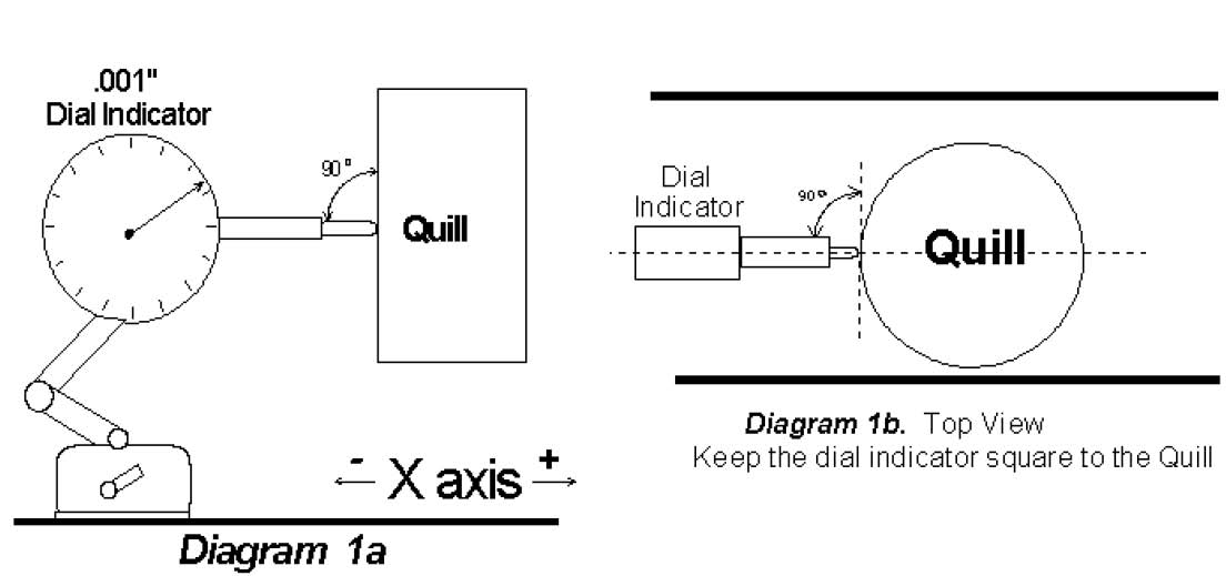
2. Set up the dial indicator parallel to the X−axis and perpendicular to the Z−axis such that the plunger will come in
contact with the quill. Be sure the quill is free from chips and grease. See diagram 1. Slow jog the X−axis until the quill just touches the plunger on the dial indicator and then stop. 3.
- Switch to Incremental Jog mode, and set the increment to .01". Note: If parameter 40 is set to 0.001 use the x10 key, however if P40 is set to 0.0001 use the x100 key.
- Continue jogging the X−axis, moving the plunger incrementally toward the quill three (3) times. Observe and
record the dial indicator start position. DO NOT TOUCH THE DIAL INDICATOR or the stand. Continue to jog the X−axis moving the plunger incrementally toward the quill ten (10) times. 6.
7. Jog the X−axis IN THE OPPOSITE DIRECTION ten (10) times. Observe and record the dial indicator finish reading. With no mechanical backlash, the start and finish values will be the same position. Subtract Finish − Start = Lash. Repeat steps 3 to 7 to verify Lash before entering value.
Enter the Lash comp. value for the X−axis and save your changes. Repeat this procedure for all axes. 8.
Notes:
- Measure the backlash several times until you achieve the same result several times.
- Measure backlash where the machine is to be operating the most (usually the center of travels). If the jobs that are being run use most of the travel envelope, measurements can be averaged.
- If you measure more than .0015" of lash, the machine should be mechanically adjusted or repaired. Although the control will attempt to compensate for excessive lash (>. 0015"), it cannot completely eliminate the underlying mechanical problems that result in unsatisfactory performance.